


How does an Electric Motor work? (DC Motor)
How an electric motor works—in theory
French physicist André-Marie Ampère (1775–1867) and it’s the basic science behind an electric motor. But if we want to turn this amazing scientific discovery into a more practical bit of technology to power our electric mowers and toothbrushes, we’ve got to take it a little bit further. The inventors who did that were Englishmen Michael Faraday (1791–1867) and William Sturgeon (1783–1850) and American Joseph Henry (1797–1878). Here’s how they arrived at their brilliant invention.
Suppose we bend our wire into a squarish, U-shaped loop so there are effectively two parallel wires running through the magnetic field. One of them takes the electric current away from us through the wire and the other one brings the current back again. Because the current flows in opposite directions in the wires, Fleming’s Left-Hand Rule tells us the two wires will move in opposite directions. In other words, when we switch on the electricity, one of the wires will move upward and the other will move downward.
If the coil of wire could carry on moving like this, it would rotate continuously—and we’d be well on the way to making an electric motor. But that can’t happen with our present setup: the wires will quickly tangle up. Not only that, but if the coil could rotate far enough, something else would happen. Once the coil reached the vertical position, it would flip over, so the electric current would be flowing through it the opposite way. Now the forces on each side of the coil would reverse. Instead of rotating continuously in the same direction, it would move back in the direction it had just come! Imagine an electric train with a motor like this: it would keep shuffling back and forward on the spot without ever actually going anywhere.
How an electric motor works—in practice
There are two ways to overcome this problem. One is to use a kind of electric current that periodically reverses direction, which is known as an alternating current (AC). In the kind of small, battery-powered motors we use around the home, a better solution is to add a component called a commutator to the ends of the coil. (Don’t worry about the meaningless technical name: this slightly old-fashioned word “commutation” is a bit like the word “commute”. It simply means to change back and forth in the same way that commute means to travel back and forth.) In its simplest form, the commutator is a metal ring divided into two separate halves and its job is to reverse the electric current in the coil each time the coil rotates through half a turn. One end of the coil is attached to each half of the commutator. The electric current from the battery connects to the motor’s electric terminals. These feed electric power into the commutator through a pair of loose connectors called brushes, made either from pieces of graphite (soft carbon similar to pencil “lead”) or thin lengths of springy metal, which (as the name suggests) “brush” against the commutator. With the commutator in place, when electricity flows through the circuit, the coil will rotate continually in the same direction.
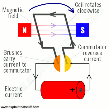
Artwork: A simplified diagram of the parts in an electric motor. Animation: How it works in practice. Note how the commutator reverses the current each time the coil turns halfway. This means the force on each side of the coil is always pushing in the same direction, which keeps the coil rotating clockwise.
A simple, experimental motor such as this isn’t capable of making much power. We can increase the turning force (or torque) that the motor can create in three ways: either we can have a more powerful permanent magnet, or we can increase the electric current flowing through the wire, or we can make the coil so it has many “turns” (loops) of very thin wire instead of one “turn” of thick wire. In practice, a motor also has the permanent magnet curved in a circular shape so it almost touches the coil of wire that rotates inside it. The closer together the magnet and the coil, the greater the force the motor can produce.
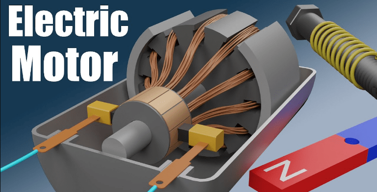
Although we’ve described a number of different parts, you can think of a motor as having just two essential components:
- There’s a permanent magnet (or magnets) around the edge of the motor case that remains static, so it’s called the stator of a motor.
- Inside the stator, there’s the coil, mounted on an axle that spins around at high speed—and this is called the rotor. The rotor also includes the commutator.
Electric motors can seem very mysterious!
How do they use electricity to start rotating?
Let’s break it down step by step to understand how it works. Topics covered in this video: circuits, current, magnets, electromagnets, armature, commutator, brushes, stator, and rotor. This video only covers DC motors.
Do not forget to share your opinion with us to provide you with the best posts !


A motivating discussion is worth comment. There’s no doubt that that you need to write more on this topic, it may not be a taboo matter but usually people don’t speak about these subjects. To the next! Kind regards!!